(1)圆弧输出设置
用于对圆弧插补的输出进行控制,如圆心的表达(R或IJK)、圆弧打断、整圆输出等。
#Arc output settings
breakarcs: 0 #Break arcs, 0 = no, 1 = quadrants, 2 = 180 arcs
arcoutput: 0 #0 = IJK, 1 = R no sign, 2 = R signed neg. over 180
arctype : 2 #Arc center 1=abs, 2=St-Ctr, 3=Ctr-St, 4=unsigned inc.
do_full_arc : 1 #Allow full circle output? 0=no, 1=yes
helix_arc: 1 #Support helix arc output, 0=no, 1=all planes, 2=XY plane only
arccheck : 1 #Check for small arcs, convert to linear
atol : .01#Angularity tolerance for arccheck = 2
(2)五轴机床构造及运动设置
用于对典型的五轴机床运动方式进行配置,可对工作台双摆动、主轴头双摆动、主轴摆动及工作台摆动、工作台复合摆动(回转)、主轴复合摆动(回转)等典型五轴机床进行设置。主轴回转或摆动对应于相应机床,可处于主动轴或从动轴的形式。针对KR214机床的配置Mtype设为2。
#Machine rotary routine settings
mtype : 2 #Machine type (Define base and rotation plane below)
#0 = Table/Table
#1 = Tilt Head/Table
#2 = Head/Head
#3 = Nutator Table/Table
#4 = Nutator Tilt Head/Table
#5 = Nutator Head/Head
head_is_sec : 2 #Set with mtype 1 and 4 to indicate head is on secondary
(3)旋转轴矢量平面设置
用于设置主动轴及从动旋转轴矢量方向,设置主轴或工作台复合摆动轴矢量方向。根据KR214(KR211)的C、A轴的运动配置,其C轴在XY平面内旋转,A轴在YZ平面内摆动,因而设置如下:
#Primary planeXY XZ YZ
#Secondary or XZ XY XY
#Secondary YZ YZ XZ
rotaxis1 = vecy #Zero
rotdir1 = vecx #Direction
rotaxis2 = vecz #Zero
rotdir2 = vecy #Direction
p_nut_restore #Postblock, restores original axis settings
result = updgbl(rotaxis1, vecy) #Zero
result = updgbl(rotdir1, vecx) #Direction
result = updgbl(rotaxis2, vecz) #Zero
result = updgbl(rotdir2, vecx) #Direction
nut_ang_pri : -45
对于旋转平面不在坐标平面的特殊主轴复合摆动或工作台复合摆动的五轴机床,且Mtype设置为3~5的特殊类型时,如DMU125P和DMU50P的机床需要正确设置Nut_ang_pri参数。只有当Mtype设置为3~5时,该参数才起作用。
(4)旋转轴中心、偏心设置及刀具轴输出设置
根据KR214(或KR211)机床运动轴配置特点,其g7_tilt参数应设为2。
saxisx: 0 #The axis offset direction?
saxisy: 0 #The axis offset direction?
saxisz: 0 #The axis offset direction?
r_intersect : 1 #Rotary axis intersect on their center of ratations
g7_tilt : 2 #With mill_plus and nutating, select toolplane output
#0 = Post selects G7 rotation axis
#1 to 4, user selected G7 rotation axis
#1 = Primary C : X zero, Secondary B
#2 = Primary C : Y zero, Secondary A
#3 = Primary C : -X zero, Secondary B
#4 = Primary C : -Y zero, Secondary A
shift_90_s : 1 #Shift pos.=1, neg.=-1
(5)机床行程及转角限位设置
坐标运动轴的行程及软件限位设置的正确性,直接影响五轴机床数控程序输出的正确性,下述分别为KR214的各坐标轴的行程及A/C轴的转角行程设置。
1)X、Y、Z线性轴行程设置
adj2sec : 1
use_stck_typ : 2 #0=Off, 1=Stock def., 2=Limits
up_x_lin_lim : 1350#X axis limit in positive direction
up_y_lin_lim : 900#Y axis limit in positive direction
up_z_lin_lim : 1400#Z axis limit in positive direction
lw_x_lin_lim : -1350 #X axis limit in negative direction
lw_y_lin_lim : -200 #Y axis limit in negative direction
lw_z_lin_lim : 200#Z axis limit in negative direction
2)主动轴C和从动轴A的转角设置
auto_set_lim : 1 #Set the type from the angle limit settings (ignore these)
pri_limtyp : 1
sec_limtyp : 1
#Set the absolute angles for axis travel on primary
pri_limlo: -200
pri_limhi: +200
#Set intermediate angle, in limits, for post to reposition machine
pri_intlo: -200
pri_inthi: +200
#Set the absolute angles for axis travel on secondary
sec_limlo: -115
sec_limhi: +90
#Set intermediate angle, in limits,for post to reposition machine
sec_intlo: -200
sec_inthi: +200
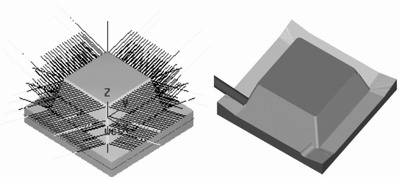
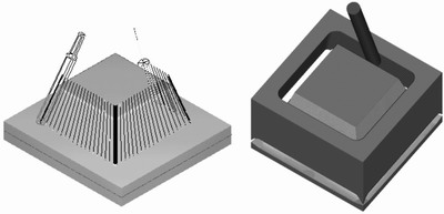
五坐标机床后处理程序的验证可通过下面的测试进行。例如,我们根据KR214的需求进行了多种测试,如X/W轴联动、固定A轴、变A轴、旋转C轴、五轴底刃、五轴侧刃等典型的五轴加工程序测试。其测试的刀具轨迹与部分程序代码如图3~图5所示。

a)五轴底刃刀具轨迹及其模拟

b)五轴侧刃刀具轨迹及其模拟
图3 五轴铣削加工功能测试示意图